

Sub-Total: $0.00
FAQs About Our Energy Load Management Device
When calculating the electrical load draw on a panel there are 2 methods of calculation depending on the model of simpleSwitch.
For the model 240, the higher of the two electrical loads is to be used for the load calculation.
For model 240CT, the device is typically not required to be counted towards the load calculation.
Check with local electrical authorities prior to purchasing product on jurisdictional code for calculating loads.
This is typically applicable when sharing power between two devices using the simpleSwitch 240 model. For devices that contain a neutral wire and use 120V power (e.g. clock on an electric range).
Typical installation examples of how to connect neutral wires together:
• Neutral wires may be spliced and the simpleSwitch 240 may be used as a junction box to house the spliced wires. Position the spliced wires in the bottom ½ of the simpleSwitch 240 housing.
• The installer may use a multitap connector or push wire terminal block (See examples below).
• If the inspector requires that the neutral block be mounted, there are mounted terminal blocks available that will mount to the inside bottom of the simpleSwitch 240.
(Example. Not Supplied)
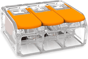
(Example. Not Supplied)
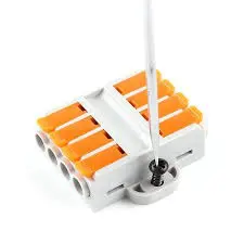
(Example. Not Supplied)
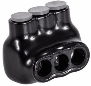
(Example. Not Supplied)
- It is very important that installer sets the car charger device PRIOR to plugging charger into the car (as damage to simpleSwitchTM may result if car charger device is not properly set).
- Electric Vehicle (EV) home chargers have settings that must be configured on the EV charger device (not the car) prior to charging with simpleSwitch.
- Simply stated, EV chargers must be set to a maximum of 32 Amps charging.
When using the simpleSwitch 240 model, there may be a need to set a delay to match the power surge current duration.
Electrical device with a surge current (e.g. Air Conditioner, other electrical devices with a surge current, typically containing a motor).
- If the simpleSwitch 240 Secondary (does not apply to the Priority) is connected to a device with a motor that will have a surge current,
set the time delay according to the duration of the surge current (typically several seconds).
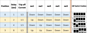
- The suggestion is to start at a 4-second delay (position 2). In the event that the simpleSwitch 240TM switches off the Secondary during the start of the AC motor (Power Surge) then set the delay to 8-seconds (position 3). In the event that simpleSwitch 240TM still switches off the Secondary device during the start of the AC motor (Power Surge) then the device being connected to the simpleSwitch 240TM may not be suitable for the simpleSwitch 240TM. Please contact technical support at (206) 494-3260 Ex 701.
- Set the dip switches according to the table below to set the time delay:
Energy Load management Projects
- Building Type: 1960's Home
- Project: A/C Install
- Panel Size: 70 Amp
- Solution: simpleSwitch Model 240CT With external Current Transformers
- Application: Power Shedding.

- Building Type: New Home Build
- Project: Two (2) A/C & Electric Heaters
- Panel Size: 200 Amp
- Solution: Three (3) simpleSwitch Model 240
- Application: Power Sharing
- Configuration 1: Priority: Heater. Secondary EV Charger
- Configuration 2: Priority: Heater. Secondary EV Charger
- Configuration 3: Priority: Heater. Secondary: A/C

- Building Type: Appartment Building
- Project: Two (2) EV Chargers each to separate meter
- Panel Size: 100 Amp
- Solution: (2) simpleSwitch Model Model 240 CT
- Application: Power Shedding
- Configuration 1: EV Charger with Tap Breaker
- Configuration 2: EV Charger with Tap Breaker


Installation Instructions:
a. simpleSwitch 240 - click here to download PDF
b. simpleSwitch 240CT - click here to download PDF
c. simpleSwitch 240 - Manuels d’installation
d. simpleSwitch 240CT - Manuels d’installation
Specification Sheets:
a. simpleSwitch 240 - click here to download PDF
b. simpleSwitch 240CT - click here to download PDF
How simpleSwitch 240 works to
"SHARE THE POWER" between 2 appliances:
simpleSwitch 240Wiring, connections & termination strip explained:
Professionals With Questions
"*" indicates required fields